Super simple and super fast to make a coaxial cable antenna for receiving digital television channels can be made with your own hands in about 5 minutes. For this, you will need absolutely nothing but the cable itself. And this is the main plus of this antenna.
No TV now.
This design will definitely help you out, for example, when you have just entered your home and have not yet managed to stretch the cable or install a stationary antenna. Of course, this is not the only example where this truly simple loop antenna can help.
Now in the comments someone will definitely write that there are antennas even simpler, such as a whip. For the manufacture of which it will be enough just to remove two insulations from the cable and everything will work. Of course, I agree with this, but the loop antenna that I will make from a coaxial cable will have much more gain, due to its directivity and resonantly closed circuit.
Making an antenna from coaxial cable
It looks like a version made of black cable.
And now the manufacture of the antenna in order. All we need is less than half a meter of coaxial cable of any color. I took white.

We retreat 5 cm from the edge of the cable and remove the upper insulation.

Next, remove the insulation from the central core.

Now we twist everything together neatly and tightly.

Then, from the edge with the insulation removed, we retreat 22 cm and cut out a piece of 2 cm of the upper insulation and shielded wire with a rope, without touching the insulation of the central core.

Now we measure another 22 cm from the end of the cut and make a cut 1 cm wide only with the removal of the upper insulation. We do not touch the cable screen.

Next, take the end of the cable from which we started. And we wrap it very tightly at the last cut, forming a circle of the antenna.


With this, our antenna is ready to go. Of course, this is not necessary, but if you hang the antenna on the street, then it is better to insulate all the bare places of the cable with electrical tape. You can also add a rigid frame, but this is optional.
Antenna location
We direct the antenna to a repeater or television tower. The direction can also be chosen empirically by rotating the antenna.The best option would be if you place it outside the window, since the walls of the house jam the high-frequency signal very strongly.

Test showed excellent performance

It is believed that the helical antenna is characterized by circular polarization, but the opinion is erroneous. In fact, the structure of the coils is such that waves with linear polarization are also received. This is convenient when it is possible to work on any wave structure. And helical antennas are used as a mirror feed on the satellite. For radio amateurs, the disadvantage is that the linearly polarized wave is attenuated by three decibels, as you know, no other is used in radio and television broadcasting. In the country, a spiral irradiator is appropriate only for catching NTV + from a satellite, the method is not used there. We will not discuss a number of special applications of these antennas. However, queries on the topic are found on the network. Who needs a spiral antenna, twisted from wire and dressed on a piece of pipe, we do not undertake to answer, even in the collection of works of radio amateurs this class of products is completely absent.
How to assemble a spiral antenna
The spiral antenna resembles an infrared heater of a specific design. In the USSR, military factories produced household appliances. Hence the similarity of parabolic plates and heaters. For assembly, you will need to find out the diameter and pitch of the wire winding, the number of turns. From the materials you will need:
- Steel sheet for the screen, of arbitrary thickness, so as not to bend from the wind and other collisions.
- A piece of wire so that it is enough to wind the turns with a margin.
- Power cable: 75 ohm for TV, 50 ohm for radio.
- Plastic pipe of the required diameter.
Helical antennas belong to the traveling wave class, the resistance of the devices is high, so that, having correctly calculated the device, it can be connected without coordination. First, the pipe is marked, with a margin, so that it can be stuck into the screen and glued. Along the axis (preferably on both sides), the winding step is marked. In the future, risks are used for leveling. Step back a couple of centimeters in front, start working with a marker. Please note that on the reverse side, the coil is displaced by exactly half a step.
The spiral is wound on the pipe without taking into account the pitch, with the required number of turns. In the future, starting from the first risk, you need to stretch the wire in the right way. To prevent further displacement, the correct position should be fixed with drops of glue. Approximately three or four per turn. In the meantime, let's make a screen.
Choose a square with a side of about five winding tube diameters. It makes no difference what the thickness of the steel is, withstand the strength characteristics. When assembled, the screen is perpendicular to the pipe.
For electrical assembly, it is necessary to drill a hole in the area of the end of the spiral (pipe base) and pass the wire inside. We make an additional hole behind the screen in the sidewall, where we pass the braid of the supply cable. Electrically, the central core is connected to the spiral, the feeder screen to the antenna screen. A structure is formed for receiving and transmitting waves. The pipe with the steel screen is connected with glue-sealant at the corner to ensure strict perpendicularity of the parts. Key points:
- The spiral and shield are made of a conductive material such as copper.
- Dielectric pipe.
Helical Antenna Calculation
Helical antennas are good at picking up any type of wave used in terrestrial broadcasting. However, to catch the radio, the axis should be directed upwards, while the screen will be located horizontally. The device has pronounced directional properties, do not expect to be able to cover a number of towers from one point. Not so easy. The radiation pattern depends on the dimensions of the helical antenna and strongly:
- If the length of the coil is much less than the wavelength, lateral radiation prevails, across the axis of the antenna. Moreover, the polarization is not circular.
- In the ideal case, the length of the coil is within the range of 0.75 - 1.3 wavelengths. In this case, we observe the main lobe of the radiation pattern, looking forward. Of course, you need a screen.
- If the length of the spiral is greater than 1.5 wavelengths, two lobes are formed, directed into the front half-plane. More precisely, it turns out something resembling a conical surface.
Indirectly (on the second point), readers have already formed an idea of the range. We expand the strip twice, using not a cylindrical, but a conical spiral (conical spiral antenna). We recommend an online calculator at http://aerial.dxham.ru/online-raschety/raschety-antenn/raschet-spiralnoj-antenny. Here it is proposed to set the frequency, the winding pitch of the spiral and the length of the emitter:
- The width of the main lobe of the radiation pattern depends on the length of the winding of the spiral. Vary the number of turns and observe the parameter (located at the bottom of the calculator page). The diameter of the winding of the spiral changes hardly noticeably. There is no explanation for this, the creators of the calculator know better. Of course, more copper will be needed, which is reflected in the corresponding parameters.
- We add that with increasing length, the gain also increases. This is a typical effect: the petal narrows - the gain increases. The area of the radiation pattern is a constant value. As Lomonosov said, if something arrives in one place, it must certainly leave in another. Note that as the number of turns increases, the bandwidth drops slightly.
- The gain depends on the winding pitch: the larger the number, the lower the gain, the narrower the radiation pattern. In our opinion, this is a mistake of the authors, because it turns out that it is more profitable to wind tightly. In addition, the wire will take less. Only advantages are shown, in practice this looks doubtful.
Of the useful properties of this online calculator, I would like to note the calculation of the minimum screen size. And about the step, check in the reference books, which we will do. By the way, a curious fact is that by default the site immediately has a WiFi frequency of 2.45 GHz. Here today helical antennas are often used.

Found: gain depends only on the number of turns. The winding pitch is recommended to choose 0.22 - 0.24 wavelength. On the site, this value is set in a wide range. We invite readers to choose a pitch by varying the number of turns. It happens that in some calculators there are errors, only a web programmer has accurate information.
By the way, the new source of information states that the screen is placed behind the helix at a distance of 0.12 wavelengths. It is added that if the screen diameter is chosen to be 0.8 wavelength or more, the side of the square is even larger: 1.1 λ. The situation is not so obvious, but imagine that the circle must fit inside - everything falls into place.
In terms of matching, the resistance of a helical antenna is highly dependent on wire thickness and decreases with increasing wire thickness. It is possible to achieve a figure equal to 75 and even 50 ohms. In this case, coordination is not required, which simplifies operation. It works at high frequencies. For example, the impedance will become 75 ohms with a wire thickness of 5% of the wavelength. Getting 50 ohms, you should take the thickness of the wire 7% of the wavelength. You can see that this is real at WiFi frequencies, which means that we calculate the parameters in this way, avoiding matching.
Please note that the calculator does not give the opportunity to set the thickness of the wire, and with the available impedance is 140 ohms. This is probably a professional trick, according to our knowledge the cable should be 50 ohms at WiFi frequencies. On the other hand, it is easy to check whether the dependence on the wire thickness is satisfied. Let's give a table and compare the result.
Calculation table
So, the frequency is 2450 MHz, we find the wavelength using a simple formula:
λ \u003d 299 792 458 / 2450 000 000 \u003d 0.1223 meters.
We find the required wire diameter for a resistance of 140 ohms:
0.1223 x 0.02 = 2.45 mm, let's check if this matches with the online calculator! We look and see: 2.4. Well, if we take into account that without rounding it turned out 2.447 mm, then we will assume that the two sources repeat each other, which means that the instructions for choosing the winding pitch (see above) can be trusted. On this, we consider that the home-made helical antenna is ready, and also find the thickness of the wire at which the resistance becomes equal to 50 Ohms: it turns out 8.5 mm. Moreover, at the specified high frequency it is difficult to provide the required conditions. Therefore, the goal of making a spiral antenna on their own is often set by computer scientists.
As for inconsistencies in the calculator, check the technical information you read on the Internet several times. We believe that we have answered the question, what is a spiral antenna, and how to make a spiral antenna. The advantage of the design is the ease of manufacture, if the patches need to be calculated, coordinated, and it’s not a fact that it will turn out, there is a good device here that meets the specified conditions, sifting out a lot of interference. On both sides (for reception and transmission) there are identical antennas to work with circular polarization, otherwise the result will become mysteriously unpredictable. A self-assembled helical antenna is a reality.
This type of antenna is well suited for long-range reception of a digital television signal. The simplicity of the product captivates, there are only two main parts: a reflector from a snow shovel and a spiral from a coil of power wire. Not a single solder joint, everything is screwed and twisted. There are no complex matching elements. However, the gain of the design reaches more than 10 dB, which allows it to be used in some cases without an amplifier. It was on this antenna without an amplifier that I received a digital television signal outside the city.
I want to remind you that any decimeter antenna is suitable for a digital broadcast channel, the difference will be only in the reception range. But not every antenna will provide the maximum gain and matching exactly at the desired frequency. No matter how complex the antenna is, it has dips and gain peaks throughout its entire range of received frequencies.
It was the spiral antennas that followed the flight of the first cosmonaut Yuri Gagarin. When the first Soviet lunar rovers, orienting the spirals, plowed the surface of the Moon, I dreamed of making the same space antenna.
 |
| Photo 2. |
There is nothing worse than unfinished business. As a basis, I choose the simplest of all types of helical antennas. This is a single-start, spiral, cylindrical (sometimes also conical), regular, that is, with a constant winding pitch or the same distance between the turns. Thus, the name of the antenna already speaks of its design. It was this design that was first proposed by Kraus J.D.
Helical beam antenna. - Electronics, 1947. V 20, N 4. R. 109.
I recommend the best reference book for radio amateurs "Antennas", edition 11, volume 2. By Carl Rothhammel. The book contains a lot of practical material for almost all types of antennas. Characteristics, parameters, practical calculations, recommendations.
From this edition, I give the characteristics of a helical antenna.
 |
| Rice. 1. |
You need to find out at what frequency digital broadcasting is in your region and convert the value of this frequency to meters. Wavelength in meters = 300 / F (frequency in MHz).
For Moscow broadcasting frequencies of two digital packages, I chose an average frequency of 522 MHz, which corresponds to a lambda wavelength of 57 cm. In this case, the coil diameter is D = 17.7 cm, the distance between the coils is 13.7 cm, the distance from the screen to the coil is 7 .4 cm, and the width of the screen must be within 35 cm.
As a screen (reflector), I needed the wrong snow shovel made of beautiful shiny stainless steel, constantly bending under the weight of snow. Practice shows that the reflector does not have to be round, and it makes no sense to make the side of the square more than two diameters of the spiral turn. I made the spiral from a network power wire with a diameter of about 2 mm, using one of its cores, without removing the insulation from it, since it is transparent for radio waves, and the copper wire does not oxidize in it under the influence of the external environment. In practice, the thickness of the wire turned out to be almost 5 times less than the theoretical one, which is why the antenna range turned out to be narrow. In the decimeter range, the antenna will receive well only a few television stations of analog broadcasting, however, two digital packages located side by side in frequency will fit perfectly in its amplification band. You will also need a 75-ohm coaxial cable with a connector. I do not recommend getting carried away with the length of the cable, especially if the antenna is without an amplifier, since 0.5 to 1 dB of gain is lost in each meter and a long cable will need a matching device. In my design, I used 3 meters of cable.
 |
| Rice. 2. |
Just something to do, wind the spiral, connect the cable to the conductor of the spiral and attach it all to the blade of the shovel. But I did not have a dielectric cylinder of the required diameter for fixing the wire of the spiral, and therefore I used rails and a sheet of dry plywood as a frame, transferring the dimensions of the antenna from the sketch to it. It would have been cooler if shovels were used instead of slats and plywood, but I only assembled the layout, and it was convenient for me to do everything on plywood. When the shell began to be wrapped in wire, the homemade product looked like the body of an aircraft. From the outside, it looked less harmless if I began to bend coils from a copper tube, as I wanted before. As I have already said, it is convenient to hide such an antenna under the ridge of a house with a roof made of soft roofing, andulin or slate, transparent to radio waves.
 |
| Photo 3. Antenna layout test. |
To test the antenna, I used the attic room, where I lifted the homemade closer to the ceiling with the help of a ladder. In this place, a phased loop with a 35 dB amplifier and a hard-to-purchase indoor antenna with a 30 dB amplifier used to work. Place test too. Vladimir region, 90 km east of Ostankino. Now a helical antenna without an amplifier works here. She “sees” the television center through: lining, glassine, 10 cm of basalt wool, lathing board, OSB plywood, bedding carpet, soft roof scales and a clot of nails of different lengths. layout.
 |
| Photo 5. Size and pitch of the previous ones antenna designs are almost the same. |
To improve the parameters of the antenna, it does not hurt to use a matching device - a transformer that provides a transition from an antenna resistance of 180 ohms to a coaxial cable with a resistance of 75 ohms. This is a plate of thin copper in the form of a triangle, expanding towards the screen. I picked up the place of attachment of the plate and its dimensions experimentally, using two plastic clothespins. At home, this is easy to do with a TV, lowering the antenna to a lower level, at which the image will be "snowy". It is necessary to move, turning the plate, and by ear, by reducing the noise level in the audio channel when receiving an analog signal that is close in frequency to the digital package, determine its location. Then solder.
Despite the absurd shape, this antenna has an advantage. She is without an amplifier, which often crashes after lightning strikes. In practice, the amplifiers failed twice during a thunderstorm at outdoor antennas located 30 meters from the overhead power pole, which was hit by lightning. At the antenna located under the roof of the house, six meters from the surge arrester, there were no cases of amplifier failure.The power supply of the amplifier itself may fail, since, as a rule, it is always energized and its resource is limited.
Another advantage is that the range of this antenna with an amplifier will be greater, by how much, check for yourself.
Addition. Changing the design of the antenna.
This year (2015) I decided to refine the self-made design of the spiral antenna, using a metal-plastic tube (metal-plastic) with a diameter of 16 mm instead of a wire. Previously assembled antennas have already undergone a similar operation and noticeably revived. The spiral antenna has also undergone recovery, but don't be fooled, the increase in signal level was only 10 percent, and the signal quality remained at the same 100 percent level.
 |
| Photo 7. Old antenna. |
 |
| Photo 8. Design change. |
For a long time I wanted to make an antenna using a tube as a material. The similarity with the moonshine still and the high cost stopped. But now the material has been found and already tested on simple antennas. It is an easily bendable tube made of high quality aluminum covered with plastic on all sides, sold in all construction markets for laying water pipes.
 |
| Photo 10. New design. |
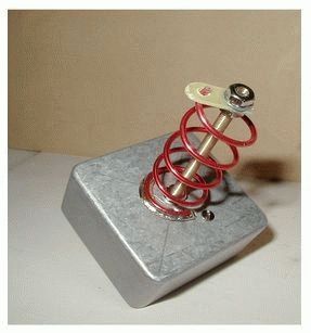
 |
| Photo 9. Bank - mandrel. |
Economic
antenna calculation.
I had to do this complicated calculation when I went to the "Everything for the Home" store, on the very outskirts of the Moscow region, and saw a metal-plastic at a price of 45 rubles. Wavelength, broadcast frequencies, circle length, number of turns, antenna gain….
I blurted out 4 meters at the checkout, summing up the economic part of the project. The prime cost of the antenna must not exceed the minimum excise value of a bottle of vodka.
Antenna calculation.
Purely for economic reasons, it turned out 6.5 turns, half a turn less than the previous homemade wire. I also took a distance between the turns equal to the fourth part of the wavelength. Similarly, I calculated the length of one turn, but for practical reasons, already having experience in the manufacture of simple loop antennas, I corrected the frequency dependence of the metal-layer, reduced the length of the turn by 1.5 cm. I also calculated the diameter of the mandrel, dividing the adjusted length of the turn by 3.14 . Taking into account the thickness of the tube, the diameter of the mandrel took 8 mm less.
Adjustment.
It consisted in measuring the SWR (standing wave ratio) with a homemade SWR meter. Initially, I measured the old homemade. Strange, but the device claimed excellent matching with a 50 ohm load (SWR = 1.5). Everything coincided with the modified antenna, however, when powered from the edge of the canvas. But constructively, later, I used the cable in the center and the SWR dropped to 2. A simple home-made SWR meter, combined with a home-made generator tuned to digital broadcast frequencies, turned out to be very useful. With its help, I was able not only to determine the SWR of the antenna, but also to check its performance, when each turn reacted to the brought lid from the saucepan by swinging the needle of the microammeter.
Results.
The design change added a gain of 10 percent, and this despite the fact that the antenna has half a turn less. In general, it receives programs in the decimeter range, operating in analog mode, no worse than a wave channel antenna (Uda-Yagi), which includes 12 directors and an amplifier with a declared gain of at least 26 dB. Both antennas are located in the same conditions at the same level from the ground. The only difference is that the operation of a purchased antenna, when receiving an over-the-air digital signal, depends on the weather and time of day, simulating a deterioration in the passage of radio waves with a characteristic quacking sound and freezing of television pictures, or even a complete absence of an image. Radio reception with a homemade antenna is always constant.
But in general, I was dissatisfied with this design, because I expected something more from it, solely based on its dimensions and the money spent. Comparing this helical antenna with the previous design homemade antenna for receiving terrestrial digital television, consisting of only two phased rings of identical diameter, made of the same material, I did not find a significant gain when comparing them in terms of reception levels.
Two phased rings and six helical rings give theoretical gains of 6dB and 10dB. Two rings in the open air and 6.5 rings under the roof, at the same level from the ground and at almost the same level of gain in percentage. Maybe the roof ate a difference of 4 dB, or maybe it's really hard to notice this difference? At the same time, do not put this coil on the street, opening this topic for unnecessary talk.
Have I lost heart? No! Amateur radio is a source of pleasure. Take up amateur radio, it's interesting. Perhaps your results will be better.
Most likely, I will return to this spiral antenna, because it didn’t fall asleep, when the “wave channel” antenna stopped receiving the air.
In the world around us, it is often very important that a person cannot do without a large amount of necessary and timely information. This information can be both peaceful and military in nature, but it is intended primarily to facilitate human activities.
Antennas are one of the types of devices used to receive and transmit information.
This course work will consider the calculation of the antenna that meets the specified technical requirements.
2. The purpose of the work
The aim of the work is to study the helical antenna of the DTsMV range, which implies the calculation of the geometric dimensions of the antenna, its radiation characteristics.
3. Brief overview of helical antennas
Helical antennas belong to the class of traveling wave antennas. They are a metal spiral fed by a coaxial line. There are quite a few varieties of helical antennas, but almost all can be reduced to the following three types:
a) cylindrical (see figure 3.1);
b) conical (see figure 3.2);
c) flat (see figure 3.3).
Figure 3.1 - Cylindrical antenna.

Figure 3.2 - Conical antenna.

Figure 3.3 - Flat antenna.
Depending on the number of spiral branches, they can be single-start (one branch), double-start (two branches), etc.
The principle of operation of helical antennas
The spiral antenna (Fig. 4.1) consists of a wire spiral powered by a coaxial line. The inner wire of this line is connected to the spiral, and the outer sheath to the metal disk.
Helical antennas form a radiation pattern consisting of two lobes located along the axis of the spiral on opposite sides of it. In practice, one-sided radiation is usually required, which is obtained by placing it in front of a screen (disk). In addition, the helical antenna disk serves to reduce currents on the outer sheath of the coaxial line, to reduce fluctuations in the input resistance in the working one. The disk diameter is chosen on the order of (0.8-1.5)l, where l is the length of the helix. The disc does not have to be made from a solid sheet, it can be made from a system of radial and circular wires.
4. The basis of the operation of a cylindrical helical antenna
Detailed studies have shown that several types of current simultaneously exist on a radiating cylindrical spiral, differing from each other in amplitude and the number of periods, which fit along the axis of the spiral with their own attenuation and with their own phase velocity. However, the shape of the directivity diagram of the spiral depends mainly on only one, the dominant wave, the type of which is determined by the ratio between the length of the spiral coil and the operating wavelength.
Let us introduce the following notation:
Operating wavelength in free space;
T q - current wave in the coil of the q-th type; q=0,1,2…. An integer indicating how many periods of the current wave fit along one turn of the spiral;
V q - the speed of propagation of the current wave T q along the wire of the spiral;
C is the speed of light in free space;
D is the diameter of a coil of a cylindrical spiral.
Three modes of operation of a cylindrical helical antenna are known:
When the length of the spiral turn is less than 0.65 (the wavelength is >5D), the T0 wave dominates on it, which is characterized by a change in the current phase within 3600 over several turns. Wave T 0 from the end of the spiral leads to the formation of standing waves, which form the radiation pattern of the antenna. Wave T 1 has a very small amplitude and does not participate in the radiation. The maximum radiation for this case is obtained in a plane perpendicular to the axis of the spiral (Fig. 4.2a) and it is not directed in this plane.
If the length of the coil lies in the range from 0.75-1.3 (the wavelength, respectively = 4D-2.2D), it is dominated by the T 1 wave, the phase velocity of which is less than the speed of light V 1 0.82 C. The T 1 wave is intensively emitted by all the coils, therefore, in the spiral a traveling current wave is established, which forms a radiation maximum along the axis of the spiral (Fig. 4.2 b). The wave T 0 also present on the helix quickly decays along the length of the helix and its contribution to the radiation pattern is small.
The axial radiation mode is the main, most used mode for the operation of helical antennas, therefore the T 1 wave, which is predominant when the length of the spiral coil wire is approximately equal to the operating wavelength, is called the main one.
With a coil length greater than 1.5 (in this case<2D), на цилиндрической спирали помимо основного типа волны Т 1 возникают волны Т 2 , Т 3 и т.д. Волна Т 1 становится затухающей, в то время как Т 2 имеет постоянную амплитуду и является определяющей в излучении. Максимальное излучение получается в направлениях, образующих острый угол относительно оси антенны, и пространственная диаграмма получается в форме конуса

Figure 4.1 - Helical antenna excitation circuit.

Figure 4.2 - spirals having different diameters and their corresponding radiation patterns.
5. Calculation of the parameters of a cylindrical antenna
The parameters of the cylindrical spiral are:
n is the number of turns of the helix,
Helix angle,
R - spiral radius,
l - axial length of the spiral,
S - helix pitch,
L is the length of the helix.
There are the following relationships between the specified parameters (see Figure 5.1):

Figure 5.1
The diameter of the helix turns and the winding pitch should be chosen so that each turn has a polarization close to circular and maximum radiation in the direction of the helix axis (Z axis). In addition, it is necessary that the strengths of the fields created by the individual turns in the direction of the Z axis add up at the reception point in phase or with a slight phase shift. According to the traveling wave antenna theory, the maximum directivity is obtained when the phase shift A1 between the field strength generated by the first (from the source) turn and the field strength generated by the last turn is equal.
To ensure circular or close to it polarization of the field, as well as to ensure intense radiation of each loop in the direction of the Z axis, it is necessary that the length of the loop be close to k. The above can be explained as follows. Assume that the coil pitch is infinitely small, then the coil forms a flat frame. As is known, in a helical antenna, the KBV turns out to be close to unity. Let us therefore assume that the traveling wave regime takes place in the helical antenna. Let us also assume that the speed of current propagation along the coil is equal to the speed of light. In this case, the phase shift between the current at the beginning and at the end of the coil is equal.
In the direction of the Z axis, the components of the field strength vectors Ex and Ey will be of the same magnitude. The phase shift between these components will be equal to /2. The latter follows from the fact that the currents in the coil elements oriented parallel to the X axis are phase-shifted by /2 with respect to the phase of the currents in the elements oriented parallel to the Y axis. The equality of the values of Ex and Ey and the phase shift between them, equal to /2, provides circular polarization. When the length of the coil is equal to and the speed of current propagation along the wire is equal to the speed of light, intense radiation is also provided in the direction of the Z axis. The latter can be approximately proved as follows. Consider two arbitrary coil elements located symmetrically about the center, for example, elements 1 and 2 (Fig. 5.2). Each of these elements has a maximum radiation in the direction of the Z axis. The vectors E created by these elements in the direction of the Z axis are parallel to the tangents to the circle at points 1 and 2. The phase shift between the currents in elements 1 and 2 due to the traveling wave mode is equal to. In addition, the currents in these elements have opposite directions, which is equivalent to an additional phase shift equal to. Thus, the fields of both elements in the direction of the Z-axis are added in phase. It is easy to show that any two symmetrically located elements create in-phase fields in the direction of the Z axis, which provides intense radiation in this direction.
The elementary presentation of the principle of operation of a helical antenna given here does not take into account the complexity of the processes occurring in it and, in particular, the fact that in reality there is a significant reflection of energy from the helix. In addition, the wave along the antenna propagates both directly along the wire and through the spatial connection between the turns, which creates a more complex picture of the current distribution.

Figure 5.2.
To ensure circular or close to it polarization of the field, as well as to ensure intense radiation of each loop in the direction of the Z axis, it is necessary that the length of the loop be close to.
The winding pitch and the coil diameter are chosen in such a way that the phase shift between the field strengths created by the first and last elements of the coil, then in the direction of the Z axis, circular polarization and maximum radiation are preserved. This will take place when the relation is satisfied:
2????????????????
Phase shift between the fields of the initial and final elements of the coil, determined by the difference in the path of the rays from these elements; - phase shift of the fields of these elements, determined by the phase shift of the currents of these elements.
From the above equation, we get the relationship between L and S corresponding to circular polarization:
If we choose the ratio between S and L in accordance with this formula, then the phase shift between the fields created in the Z direction by adjacent turns will also be equal to 2. Thus, the fields of all antenna turns add up in phase, which ensures maximum radiation in the Z direction. However, this mode of operation of the helical antenna does not correspond to the maximum directivity factor. The maximum directivity factor is obtained when the phase shift between the fields of the first and second turns is equal to. This requires that:
where n is the number of turns of the helix.
From (5.3) we find the relation between and S corresponding to the maximum value of the directivity factor:
If relation (5.4) is satisfied, however, a purely circular polarization is not obtained, and the level of the side lobes somewhat increases. The non-uniformity coefficient of the polarization characteristic in the direction of the spiral axis is equal to:
If these antennas are selected in accordance with formula (5.2) or (5.4), then good directional properties are maintained in a significant range, lying approximately in the range from 0.75 to 1.3, where is the wave for which the optimal ratio between L, C / V1, n and S.
Antenna calculation:
Initial data for the calculation of the antenna
Operating wavelength range: min=0.48 m
40 degree half power beamwidth
Calculation of the geometric dimensions of the antenna
Let's choose the average value of the wavelength from the given range:
On the basis of experimental studies, the following empirical formulas were obtained, valid for 5 Half power beamwidth, expressed in degrees: Coefficient of directional action (KND) in the direction of its axis: Input impedance The pitch of the helix can be found from condition (5.2), if it is necessary to obtain circular polarization, or from (5.4), to obtain the maximum directivity. Let us need circular polarization, then the pitch of the helix is Satisfies the condition 12 0<<15 0 , значит мы можем применить формулы, полученные на основании экспериментальных исследований: To find the length of the antenna, we express l=nS from (5.7) when condition (5.9) is satisfied: So the number of turns is: For further calculations, round the number n up to an integer: n=8, then l=nS=0.986m(5.14) The radius of the spiral will be equal to (see Fig. 5.1): from here The input impedance of the antenna in the axial radiation mode remains purely active, since in this mode the traveling wave mode is established in the helix wire. Let us need to get the maximum DPV, then In order for the antenna radiation to be axial, we take the length of the helix turn equal to the average wavelength of the specified range: the pitch of the helix is The winding angle of the turns will be equal to: Satisfies the condition 12 0<<15 0 , значит мы можем применить формулы, полученные на основании экспериментальных исследований: To find the length of the antenna, we express l=nS from (5.7) when condition (5.18) is satisfied: So the number of turns is: For further calculations, round the number n up to an integer: n=6, then l=nS=0.846m(5.23) The radius of the spiral will be: The length of the wire for winding the spiral will be equal to: Directional Coefficient: Input impedance For both cases: The screen disk diameter is assumed to be (0.9-1.1) sr The diameter of the wire of the spiral is selected on the order of (0.03-0.05) sr Beam calculation: Approximately, we can assume that the amplitude of the traveling wave in the spiral is constant. Then the radiation pattern of the antenna can be represented by the product of the radiation pattern of a single turn by the radiation pattern of an array of n omnidirectional radiators, where n is the number of turns: where is the angle relative to the helix axis. This approximation is valid the more, the more turns n the spiral has and the smaller the step angle. The radiation pattern of a single loop is approximately described by the expression The lattice factor is known to be Applied to a helical antenna phase shift between the currents of adjacent turns. Given that С/V1=1.22, to calculate the radiation pattern of a cylindrical helical antenna, we obtain the following approximate expression: As a result, when obtaining the maximum directivity factor, we will have radiation patterns for three values of wavelengths: min, cf, max: When obtaining circular polarization, we will have radiation patterns for three values of wavelengths: min, cf, max: Antenna matching with coaxial (Zv = 75 ohm) There are several ways to match the antenna with the coax: Coordination with a quarter-wave transformer: Coordination of an antenna with input impedance Z3=120 ohm with coax Z1=75 ohm is carried out by a piece of coax with =95 ohm, length L==0.14m, and antennas with input impedance Z3=154 ohm with coax with =110 ohm Coaxial cone line termination Coordination is carried out by non-reflecting cones, an integer number of half-waves long, by making conductors in the form of corresponding linear cones. Moreover, the longer the length of the matching link (more half-waves fit), it will be better to coordinate with the antenna. 6. Conclusions on the work done helical antenna radiation polarization In the process of completing the course project, a single-pass cylindrical helical antenna was calculated: the geometric dimensions of the antenna and the radiation characteristics of the antenna. Since the operation of a helical antenna is based on circular polarization, this type of antenna is referred to as a wide-range antenna. Below are the results: helix pitch S = 0.053 m; length of the spiral turn = 0.192 m; spiral radius = 0.03 m; spiral length Lz = 0.567 m; directivity factor D = 30 dB; antenna input impedance Rin = 31.7 Ohm; the number of turns of the spiral N = 6; helix winding angle = 16 degrees; antenna disk diameter = 0.652 m; working wavelength = 0.175 m. List of sources used Aizenberg G.Z., Yampolsky V.G., Tereshin O.N. Antennas VHF.- M.: Svyaz, 1971. In 2 parts. Zhuk M.S., Molochkov Yu.B. Design of lens, scanning, wide-range antennas and feeder devices. - M.: Energy, 1973.- 440 p. Voskresensky D.I. Calculation and design of antenna arrays and their radiating elements Yurtsev OA,... Spiral antennas. - M.: Soviet radio, 1974. - 224 p. "Transmission lines of centimeter waves", part I-II. Per. from English, ed. G.A. Remeza. Publishing house "Sov.radio", 1961 I decided to single out this comment, which I will give below in the text, in a separate article. Its author got a spiral antenna, which, in the worst reception conditions, ensured the operation of two TVs simultaneously, and without amplifiers and splitters. He called his design BISPIRICAL, although this name is already combined with double helical and two helical antennas, which are presented in different versions and for different functional purposes. However, from the above example, you will understand that this is something else that still needs to come up with a name. BISPIRICAL I made a 7-turn helical antenna, designed for the 31st channel. The frame is based on 4 segments of a polypropylene water pipe (small tangent!), for a square spiral - a single copper stranded wire with a cross section of 4 square meters. mm in vinyl insulation, five meter cable. The result is quite satisfied, confident reception of both packages. I tried to make a similar antenna according to the size of the 51st channel (714 MHz), the result is that it “does not catch” the 31st channel. From this I concluded: the calculation of a spiral antenna should be performed on a low-frequency channel. Conclusion number two: the broadband of a helical antenna is due to its design (as Carl Rothammel claims), and not to the diameter of the wound wire. Build a second antenna - clutter up the balcony .... P.S. If there was an "insert image" button, I would attach a photo. Well, now it's my turn.
It's hard not to agree that this is very important information. It remains only to regret that the resource of this blog does not provide support for comments with photographs. Yes, and this comment itself did not immediately appear, but I found it by chance on the sidelines of the blog and squeezed it into the right place only two weeks later. Immediately in the course of the commentary, I’ll just clarify that when two spirals are added, as well as other antennas with directional properties, their total gain increases by only 3 dB if the gain reading of these antennas comes from a half-wave vibrator (at least that’s what the author of the two-volume book says “ Antennas ”Carl Rothammel and“ Handbook of a radio amateur designer ”under the general editorship of R.M. Malinin). The experience of the author of the attached comment practically proves that the worse the conditions for the propagation of radio waves, the stronger the advantage of circular polarization that helical antennas have, and even taking into account losses of 3 dB in the case of receiving a signal from a television transmitter with horizontal polarization. Now you need to come up with the name of this homemade antenna, which the author tested. In order not to get confused in the terminology of helical antennas, I decided to take an interest in already known names, and thus, it turned out I also note that of the entire variety of antennas, only spiral ones are in the lead in the number of geometric shapes and their corresponding names, and as for two or more spirals, the names increase proportionally. Helical antenna with horizontal polarization. These are two spirals, with opposite winding pitch, located parallel to each other in a horizontal plane, with one common reflector, with a recommended distance between the axes equal to 1.5 wavelengths. If the spirals are located in a horizontal plane, then they have horizontal polarization, if in the same plane above each other, then polarization is vertical. Two spirals of six turns each give a gain of 14 dB when compared with a half-wave vibrator (recall that 6 turns according to the table of the same edition is 11 dB). Over 120 ohm single helix, double helixes have the advantage of having a total resistance of 60 ohms and are easier to match with 50 or 75 ohm coax. With the same type of stacking of spirals, the polarization will be circular. Less commonly used is the design of a horizontally polarized helical antenna, where two helices with different winding directions are connected along the same axis. Double helical antenna. In the same two-volume book (special types of antennas for VHF and UHF bands, chapter 26. 8.) there is another term “ double helix antenna”, in fact, this antenna is comparable in properties to a quarter-wave pin, where the latter is made in the form of a spiral, and a spiral of a larger diameter performs the function of a counterweight.![]()
![]()

![]()
![]()


The seller dissuaded from buying a DVB-T2 receiver: “If you bring it back, it won’t be caught by us!” Between the source and my city 35 km. The distance is not threatening, but three lines of power transmission line-500, power transmission line-750 are arranged across - sources of interference. In addition, the direct signal is obstructed by a hill with a dense building of 16-storey buildings.31st (551 MHz) and 51st (714 MHz) frequency channels.
The first two-ring antenna was manufactured and tested. She helped to find the only option for the direction of reception, showed "glimpses" of a TV signal reflected at an acute angle from a nine-story building standing in half a kilometer.
Everything was great until the wife asked her to arrange a TV set in the kitchen as well. A serious distance (plus 13 meters) of high-frequency signal transmission is a problem. The use of a crab, as well as the inclusion of receivers in a train, did not lead to a result. I tested three models of SWA amplifiers, with the best of them the signal intensity grew from 70 to 90, but the quality at the far was not at all! Separately, receivers with this antenna ensured reliable reception of both packets.
The decision has come. What if a second spiral is arranged on the same frame, placing the turns between the turns of the first? No sooner said than done, the revision was completed in 1.5 hours. The result is wonderful! For the second helix, I used a wire with a silver-plated screen winding. The intensity and quality of the signals at the far (!) receiver have grown by 15 points. The influence of receivers on each other with such an antenna was not noticed.
It is known that when the signals from two spirals are added, the signal intensity doubles. I did not try to connect the spirals, but it would be interesting. It is also interesting to try four spirals on a common frame ...
I hope that this information will be useful to the inquisitive and handy!